Purpose:
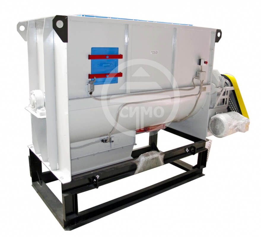
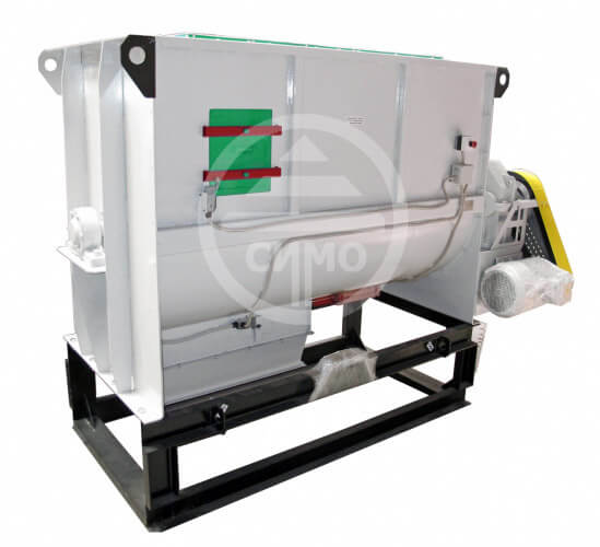
The batch-operated horizontal counterflow mixer is designed for mixing feedstuff ingredients. The mixer may be applied at feedstuff plants and in the fortifier production departments.
Specifications:
| Parameter |
ЗМГ-1000 |
ЗМГ-2000 |
| 1. Capacity, t/h |
3 |
6 |
| 2. Volume, m3 |
1,2 |
4,5 |
| 3. Mix homogeneity rate, % |
95 |
| 4. Mixing cycle, min. |
4 - 5 |
| 5. Loading time, sec. |
7 - 15 |
| 6. Discharge, min. |
1,5 - 3 |
| 7. Rotor speed, RPM |
28 |
| 8. Installed power, kW: |
| - mixer rotor |
5,5 |
11,0 |
| - unloading screw |
1,1 |
1,5 |
| - gate valve of mixer unloading* |
0,12 |
| - gate valve of over-the-mixer hopper** |
0,12 |
| 9. Dimensions: |
| - length |
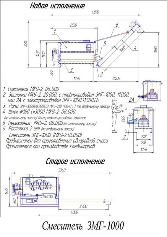
3 500 |
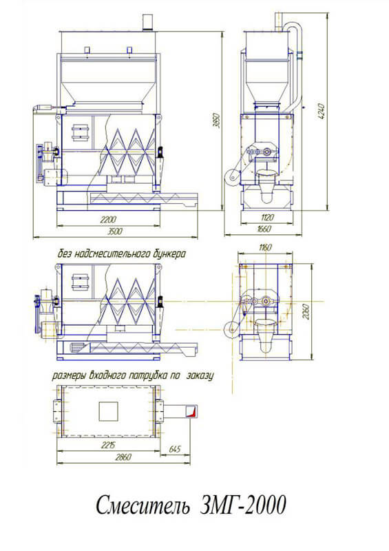
3 500 |
| - width |
1 250 |
1 660 |
| - height with over-the-mixer hopper |
3 500 |
4 240 |
| - height without over-the-mixer hopper |
1 700 |
2 050 |
| 10. Weight, kg: |
1 400 / 1 000 |
2 400 / 2 000 |
*Mixer design versions provide different gate valve drive by pneumatic cylinders (optionally**).
Structure and Operating:
Horizontal mixer consists of the body (1), rotor (2), drive (3), frame (4), electric (pneumatic) gate valve of mixer unloading (5), unloading screw (6), ** over-the-mixer hopper (7), ** electric (pneumatic) gate valve of unloading over-the-mixer hopper (8) (**optionally).
Body-1 is the steel welded construction of semi-cylindrical shape. Windows closed with the covers are designed in the side walls of mixer body for repair works, visual inspection and periodic cleaning. Body dismountable construction allows rotor disassembling. Rotor-2 is the shaft with 4 spiral paddles: 2 internal and 2 external with opposite winding. Rotor shaft is supported by bearings installed on the end walls of mixer body. Drive-3 provides specified rotor speed from the electric motor through V-belt transmission and reduction unit. Frame-4 is the welded construction for mixer installation to foundations. Gate valve of mixer unloading-5. Compound feed mixture unloading is carried out through windows in the body bottom part, which are blocked by the gate valve during mixing process. Gate valve is represented by sheet, bent along the radius of mixer body. Gate valve is operated by electric or pneumatic drive. Gate valve opening may be regulated by limit switches. Unloading screw-6 is designed for compound feed mixture remove from under the mixer and transportation along the mixer to 1-1,5m distance for supply to the following mechanism (bucket elevators, conveyors etc.).
Operation concept of the mixer is following: dosed components entering to the over-the-mixer hopper are storing up until a portion is reached. Further, products are quickly discharged to the mixer body for 8-12 seconds (short loading time prevents delamination of components), in the mixer body, components under rotation of the screw rotor are subjected to intensive back mixing by internal and external blades-spirals. On expiration of mixing time, gate valve opens and resulting mixture is directed by outer screws to the discharge point from the body and then unloaded from the mixer by screw.


