Purpose:
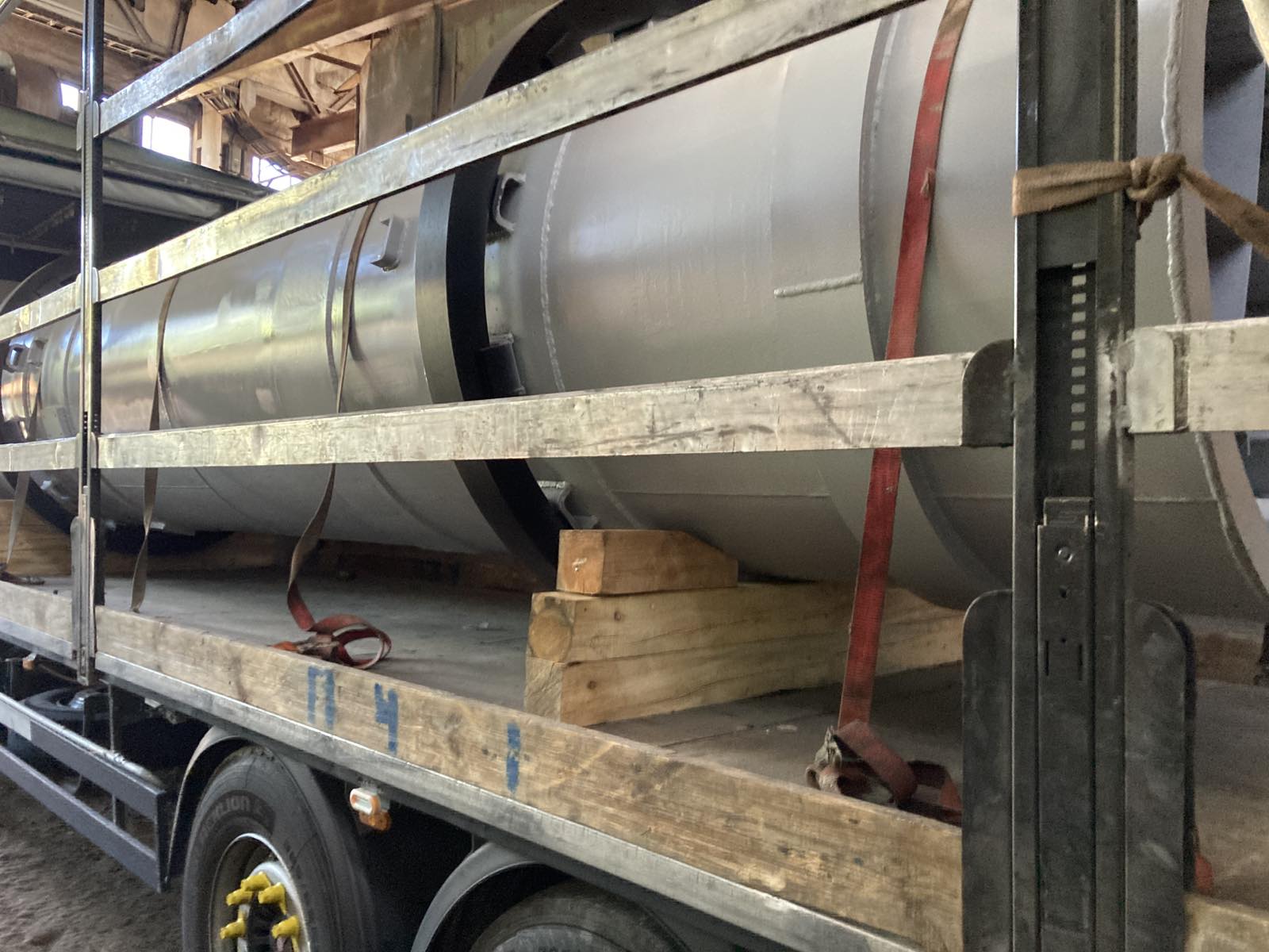
The drying drum is designed for bulk materials drying by flue gases in the chemical and building industries.
Drying drums are used in the building materials industry in different technological lines for thermal drying of limestone, clay, sand, chalk and other bulk materials with particle size up to 35 mm.
Specifications:
| Parameter |
СМ-1013 |
| 1. Type |
flow |
| 2. Mode of work |
continuous |
| 3. Dimensions of the drum housing (length х diameter), mm |
8 000 х 1 600 |
| 4. Drum volume, m3 |
16 |
| 5. Drum rotational speed, RPM |
3,14 / 4,15 / 6,2 |
| 6. Drum housing inclination to the horizon, degrees |
2° 52' |
| 7. Heat-transfer fluid |
flue gases |
| 8. Temperature of heat-transfer fluid, °С: |
500 / 600 / 800 |
| 9. Dimensions (length х width х height), mm |
9 850 х 2 550 х 3 550 |
| 10. Weight, kg |
11 500/ 11 600/ 12 900 |
| 11. Installed engine power, kW |
8 / 10 / 11 / 12,5 |
| 12. Engine rotational speed, RPM |
750 / 1 000 / 1 500 |
| 13. Supply voltage, V |
380 |
| 14. Gearbox |
1Ц2У-250-31,5-21 |
| 15. Regulatory document |
У 4845-005-54028986-2008
Code ОКП 484500 |
Construction:
Drying drums are used in the building materials industry in different technological lines for thermal drying of limestone, clay, sand, chalk and other bulk materials with particle size up to 35 mm.
Drum dryer consists of housing, support units, drive, braces, toothed ring gear. The housing is welded construction, which is made of shells. Nozzles are installed inside the housing to activate heat transfer. In the beginning of the housing, screw nozzle is installed. In the end of it, the sector nozzle is installed. In the middle – the rotary vane nozzle. The housing is supported by two steel braces. The housing is supported by special supporting units.
The toothed ring gear is mounted on the housing due to platens. This gear helps drum to rotate. The drive consists of drive gearwheel, gearbox and electric engine, which connected one other by coupling. The coupling is on the frame.
The discharging chamber serves to outlet of flue gases and to unload dried material.
The drum is set at an angle of 20° to the horizon. The inclination of the housing combined with rotation around the axis ensures that the material moves in the direction of the discharge chamber.
Hot flue gases go to the housing and heat the housing. The gases vaporise the moisture in the housing. Heat transfer occurs in three main ways. First, it transferred in suspension as the material falls from the blades. Second, it is transmitted from the flue gases through the outer surface of the material (in the pile pit). Third, is transmitted from the more heated parts of the drum interior and the casing (housing) shell.
Drying modes are changed depending on raw humidity on drum input. This also depends on the required moisture content of the finished product at the drum outlet, the fractional composition of the material to be dried, and the material properties. The temperature of the heat transfer agent supplied to the drum should not exceed 800°C. Flue gas temperature at the outlet of the drum should be not less than 100-150°C to avoid the possibility of moisture condensation in the discharge part of the drum. The rarefaction charge at the flue gas inlet to the drum must be at least 30 Pa. The fuels used are natural gas, liquefied gas, diesel fuel.