Purpose:
Self-balancing plansifters РШ-4, РШ-6 (hereinafter plansifter) are designed for sorting into fractions by size of wheat grain at the flour mills. Plansifter can be used for sorting grinding grain of other crops.
Plansifter can be used in closed room with an explosive zone of class B-Pa according to “Electrical installation rules” (EIR) and production category “B” according to SNiP P-90-81 at temperatures from plus 10 to plus 45 ° C. Plansifters are produced in climatic version У3 under State Standards 15150-69 with tropical climate.
Specifications:
| Name of indicators |
РШ-4 |
РШ-6 |
| 1. Technical productivity (load) on the 1st torn system, t/h, not less |
16* |
23,5* |
| 2. Average recovery factor of all components,%, not less: |
|
|
| - on the 1st torn system (with a technical productivity of at least 4 t/h per one section) |
64* |
64* |
| - on the 1st grinding system (with a technical productivity of at least 1.7 t/h per section) |
94* |
94* |
| 3. Number of sections, pcs. (receptions) |
4 (4) |
6 (6) |
| 4. Number of receiving devices, pcs. |
2 |
2 |
| 5. Total nominal (useful) sieve area, m2 |
18 |
27 |
| 6. Body vibration frequency at idle speed, s-1 (vibrations per minute) |
-3,7 (220) |
-4,0 (220) |
| 7. Radius of circular oscillations of the body, mm |
45 ± 2 and 41 ± 2 |
47 ± 2 and 40 ± 2 |
| 8. Air consumption for aspiration, m3/h, within (for mills with mechanical transport) |
720 - 1 020 |
960 - 1 440 |
| 9. Aerodynamic resistance, Pa, ranged |
150 - 300 |
150 - 300 |
| 10. Rated power, kW |
4 |
4 |
| 11. Overall dimensions, mm, no more |
| - length |
2 430 |
3 090 |
| - width |
1 440 |
2 020 |
| - height to the receiving board |
2 370 |
2 370 |
| 12. Weight, kg, no more |
2 030 |
3 050 |
Note:
1* Indicator values for sorting wheat grain milling products.
2** Based on technical performance on the 1st torn system.
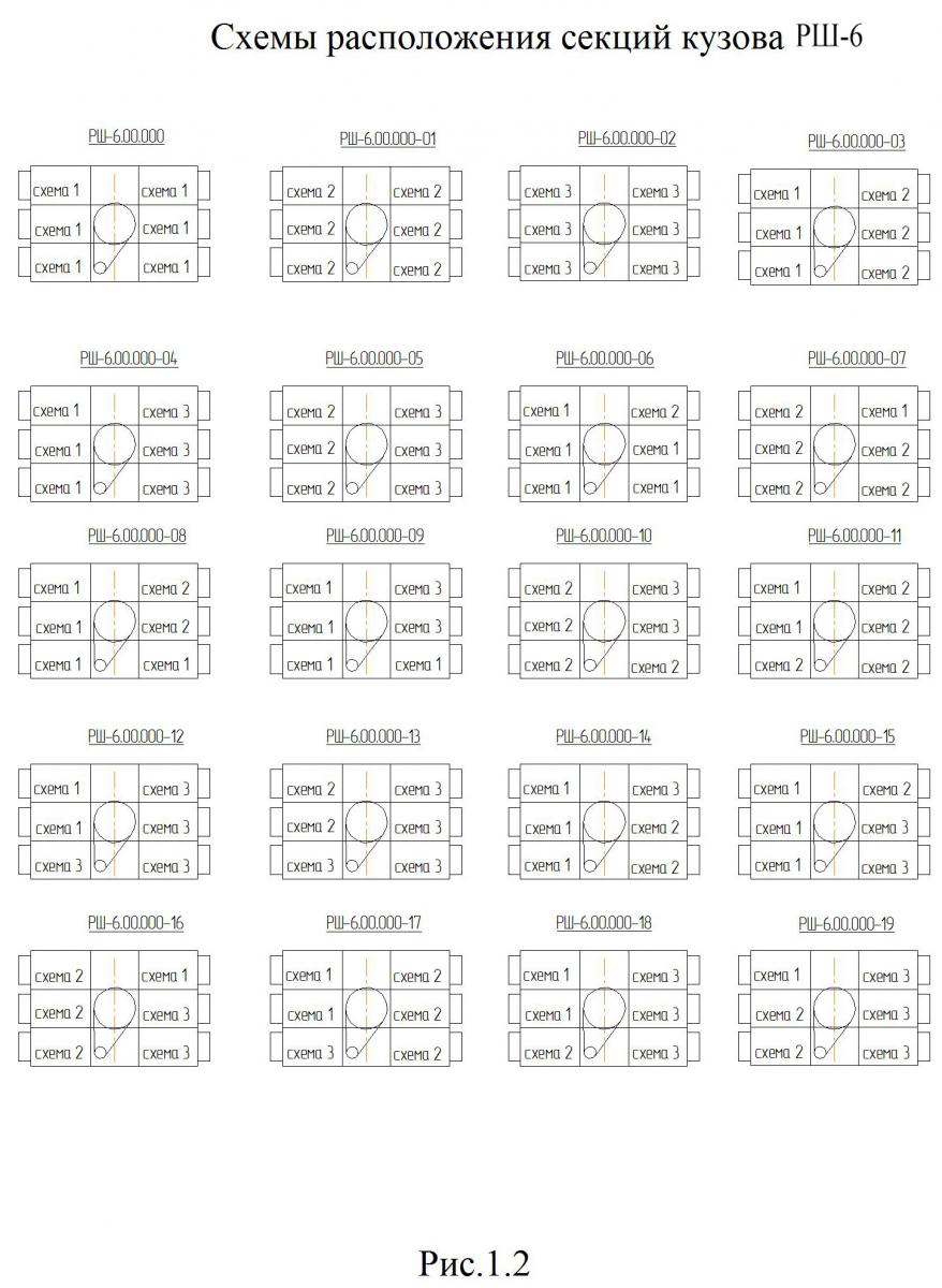
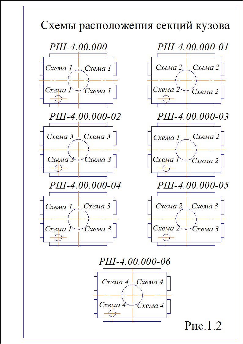
Plansifter can be manufactured in seven versions which differ in functional diagrams of sections, which location is given at Pic.1.2.
Design and operation:
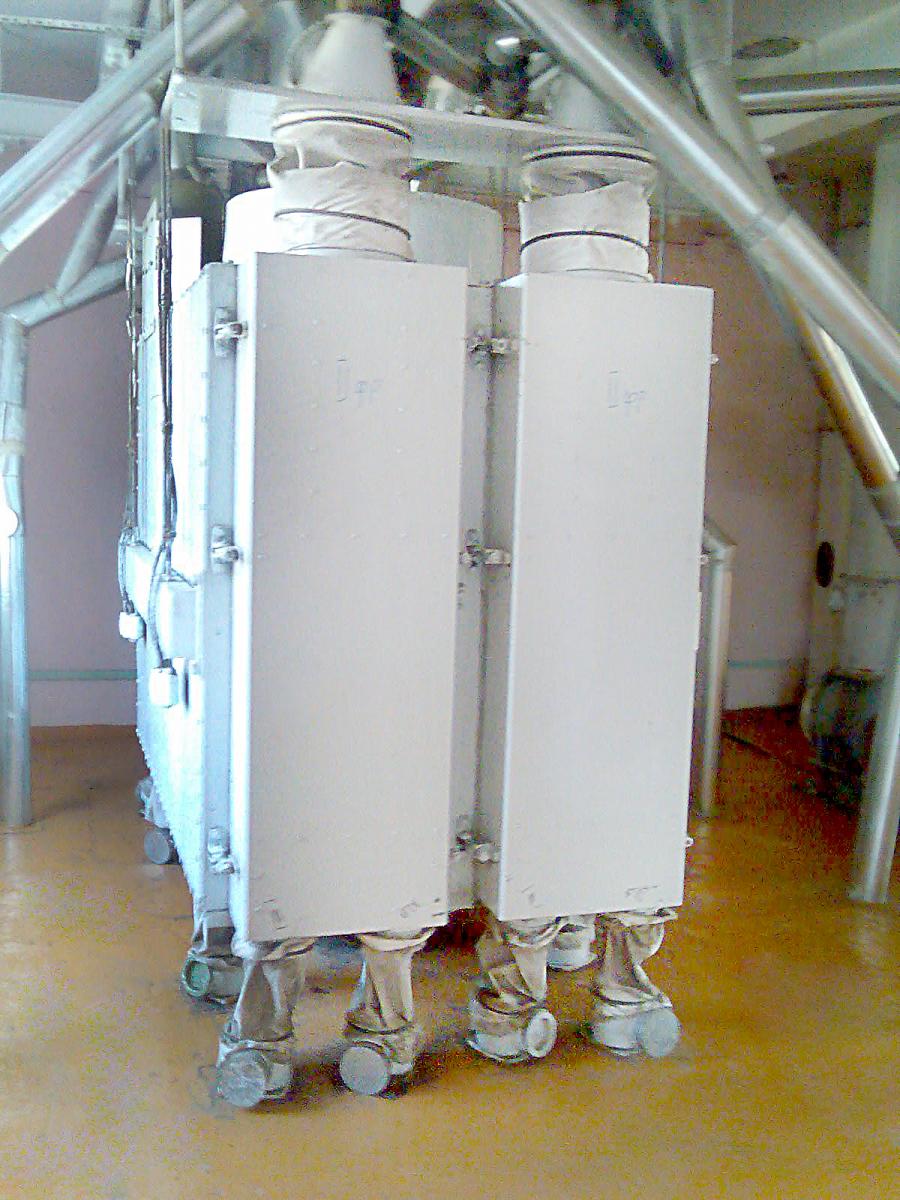
Plansifter is the prefabricated cabinet-type structure with pull-out sieve frames. Body of plansifter 12 (Pic. 1.4.1) suspended from the ceiling of the production room on four ropes 9 using hangers 2. The ends of the ropes are fastened in the locks 11 installed on the side beams of the body using wedges 24. Two receivers 4 are suspended from the ceiling on rods 3 and holders 1 above plasifter’s body. Under the body on the floor, floor nozzles or nozzle blocks 16 and 17 are installed. Inlet nozzles 25 and floor nozzles are connected to body nozzles 19 and 23 by sleeves 15 and 18. The sleeves are attached to the nozzles with clamps.
The body consists of a cabinet where a bracket 8 with a drive 5, assemblies of a balancing mechanism 6, fences 7 and 14 are installed. Transport boxes 22 and branch pipes 23 for the release of products from the cabinet section are attached to the bottom of the body. The plansifter’s cabinet consists of a supporting frame 13, to the partitions of it four frames of section 20 are attached. In the guide frames of each section, 18 sieve frames with pallets are installed. The outer casing of the cabinet, the frame partitions and the frame guides form the side by-pass channels. The frames of the sections are closed from the outside by doors 21, removable boxes and walls of which form bypass channels on the product receiving side. On the side opposite to the product intake, the section bypass channels are made in the form of removable boxes and walls attached to the brackets of the rear struts of the section frames. On the roof of the cabinet, above each section, there are branch pipes (feeders) 19. On the side walls of the cabinet, beams 10 are fixed. The cabinet frame is welded, consists of a steel pipe with flanges for the bearing housings of the balancing mechanism and four partitions to which the roof, bottom, and section frames are attached plating. The frame of the sections consists of two panels, connected by links. Each panel consists of two posts where the frame guides are attached. Steel corners and legs are riveted to the uprights to secure the section firmly in the cabinet. The posts also have two wooden plugs, which, together with the overlap, make it possible to block the side channel of the section. Depending on the version of the panel, the number of overlaps in the panel may be one, two, or even there may be none.
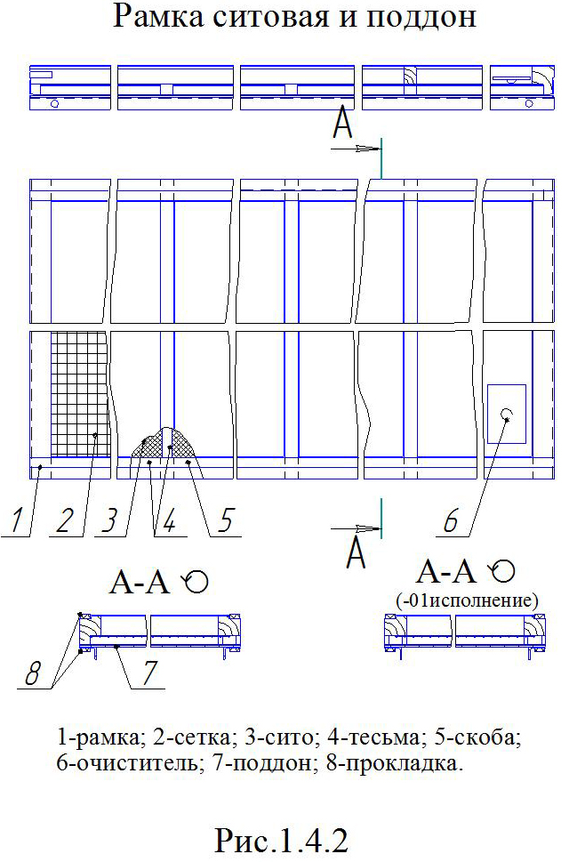
The plansifter frame (Pic. 1.4.2.) is made of wooden blocks. The frame is divided by bars into 4 cells. Cleaners designed to clean the sieves are inserted into the liners before the sieve packing in flour mills. The cleaner is a piece of cotton strap with a metal ball-head rivet inserted underneath. Sieve frames can be made in two versions: single-pitch and double-pitch. In single-slope frames, the sieve passage is released only in one direction / in one side channel /; in gable ones - in both directions. The pallet 7 is a sheet with bent ends on the short side and two corners attached from below, which serve to fix the pallet in the sieve body section, to remove the pallet with a frame from the section, and also to give it the necessary rigidity. To prevent mixing of separate product fractions, as well as for more free movement of the frames along the guides of the sections, pile fabric pads are glued on the longitudinal bars of the sieve frame and at the corners of the pallet. Bike pads are glued between the frame and the pallet, as well as on the middle blocks. Sieves in flour mills can be nailed or stapled with pistols through the web.
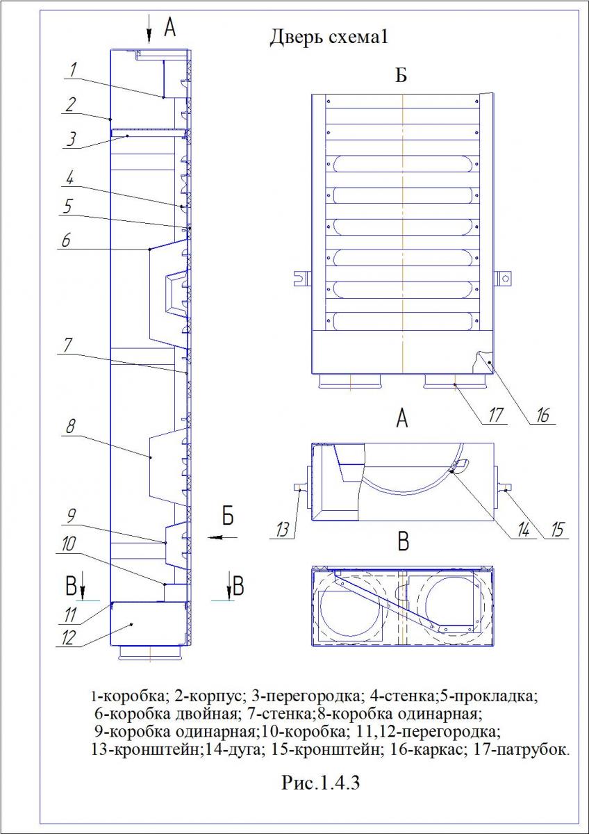
The plansifter door consists of body 2 (Pic. 1.4.3), frame 16, bypass boxes 6, 8, 9 and 10, walls 4 and 7, partitions 3, 11 and 12, two outlet pipes 17 and gaskets 5, sealing the joints of the elements doors and between the door and the cabinet section. The box-shaped door body is made of sheet aluminum alloy. Brackets 13 and 15 are installed on the sidewalls of the door for hanging the door and for pressing it against the cabinet section. On the top wall there is a semicircular hole, edged with a corner and a gasket, designed to ensure a tight fit of the door to the feeder located on the cabinet roof. The frame serves to make the door more rigid and to attach removable door elements to it. The frame is a welded frame structure made of a corner and three chords from channels. The sets of bypass boxes and walls installed in the doors correspond to certain functional diagrams. They serve to form streams of various product fractions resulting from screening on sieves in the screening sections. The frames and walls of any door are interchangeable and can be installed as overflow boxes and walls inside the section. In order to reduce the mass of the sifting, parts of doors, frames, cabinet cladding are made of aluminum alloys.
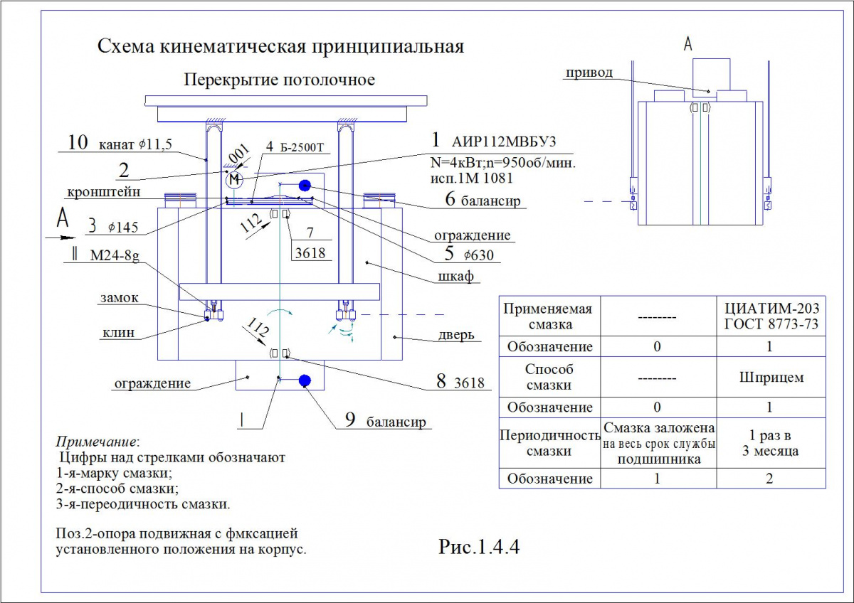
The plansifter body is driven by a V-belt drive from an electric motor. The drive motor is mounted on a bracket fixed to the cabinet. The belts are tensioned by moving the engine along the grooves of the plate using tension bolts. The kinematic sieving scheme is shown in Pic. 1.4.4.
The balancing mechanism consists of a shaft 6 (Pic. 1.4.5) installed in bearing supports 5 and 7. At the ends of the shaft, balancers 1 with replaceable weights 2 and 3 are fixed, which are necessary to regulate the radius of circular oscillations of the body. Pulley 4 is installed on the shaft under the upper balancer.
Feeders installed on the roof of the cabinet serve for uniform distribution of the initial product on 3 sieve frames and consist of a nozzle 2 (Pic. 1.4.6), a cone 1 and a disk with a plate 3. The disk has 12 holes for the product passage. With the help of ramps 4 and 5, located on the nozzle, the incoming product is divided into three equal parts.
The receiving device is designed for feeding grain grinding products into the plansifter body and for aspiration of the body. It consists of frame 1 (Pic. 1.4.7), two receiving boxes 2 and branch pipes 4. The frame of the receiving device is welded from bent profiles. Plates with holes are provided for receiving boxes. There are holders and rods for attaching the receiver. Inlet pipes are designed for connecting gravity and aspiration air ducts. The branch pipes for receiving the product are equipped with sight glasses 3.
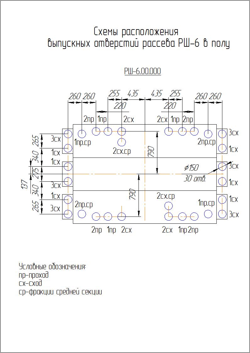
Floor nozzles are used to receive separated product fractions from the plansifter body. There are two types of floor spigots: single and double (nipple block). The design of the nozzle blocks is shown in Pic.1.4.8. The upper branch pipes 1 are connected by fabric sleeves with the body branch pipes, the lower 4 have flanges for connecting gravity flows to them using standard clamps. For sampling, the upper branch pipe has a hole closed with a plug 2. The base of the branch pipes is box 3, which is poured with concrete after the plansifter is installed. The holes on the sides of the box are designed for easy installation of branch pipes during installation.
Floor nozzles are used to receive separated product fractions from the plansifter body. There are two types of floor spigots: single and double (nipple block). The design of the nozzle blocks is shown in Pic.1.4.8. The upper branch pipes 1 are connected by fabric sleeves with the body branch pipes, the lower 4 have flanges for connecting gravity flows to them using standard clamps. For sampling, the upper branch pipe has a hole closed with a plug 2. The base of the branch pipes is box 3, which is poured with concrete after the plansifter is installed. The holes on the sides of the box are designed for easy installation of branch pipes during installation.
The plansifter is driven by an AIR112MV6UZ engine (power 4 kW, rotation speed 950 rpm). The electric motor must be powered from a three-phase alternating current network with a frequency of 50 ± 1 Hz, a voltage of 380 V. The electric sieving circuit (Pic. 1.4.10) provides for turning on and off the motor, protecting the motor and electrical wiring from short-circuit currents, overload, and minimum voltage.
When button B.2 is pressed, the magnetic starter KM is triggered and itself blocked, which connects the motor to the power network with its contacts. The engine is stopped by pressing button S B.1.
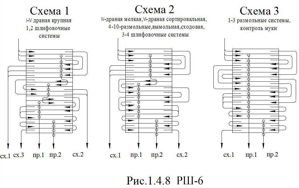
The principle of operation of the plansifter consists in the parallel and sequential sifting of the product through a set of flat horizontal sieves making a circular translational motion.
The initial product from the receiving boxes enters the feeders, from where it is distributed into three streams and is directed to the sieve frames of the body, with the help of which the screening process takes place.
The movement of the product inside the sections is carried out according to one of the functional schemes. The product fractions are discharged from the body through the outlet pipes, enter the floor pipes, and then into the gravity flow of the enterprise.
Using the product:
During the operation of the plansifter, special attention should be paid to:
- ensuring continuous supply of products to the plansifter section;
- ensuring reliable removal of products from the plansifter;
- body tightness; dust emission at the joints is not allowed;
- no contamination of one fraction to another;
- condition of all vibrating assemblies and parts, noiseless operation;
- cleaning the sieves, checking the efficiency of the cleaners during the period of stopping the plansifter;
- aspiration efficiency (for mills with mechanical transport).
The plansifter should be started and stopped without load.
The efficiency of the separation process and the coefficient of extraction of continuous fractions in the plansifter depends on the properties of the initial product, the load and the kinematic parameters of the plansifter - the frequency and radius of vibration of the body. Establishing the optimal kinematic plansifter mode should aim to obtain the best technological effect. It should be borne in mind that for sifting grinding products of torn systems (large and small), large body oscillation radii are preferable, for 3-9 grinding systems and less flour control. For other systems, the value of the oscillation radius is intermediate. The radius of the trajectory of uniform circular translational vibrations in the horizontal plane of the plansifter body is regulated by removable weights mounted on the balance bar. The dependence of the radius of circular oscillations of the body on the mass of removable loads is shown in Pic. 2.3.
When installing removable weights, it is necessary to ensure that the weight and their location on the upper and lower balancers are the same. If this condition is not met, forces are unfavorably distributed in the bearing assemblies, the horizontal movement of the body is disturbed, and the effect of product separation deteriorates.
-
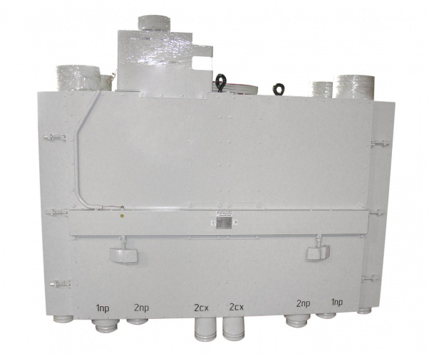
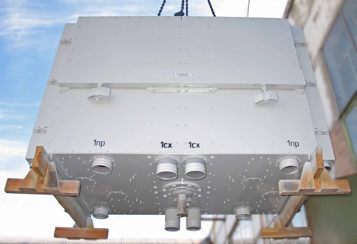
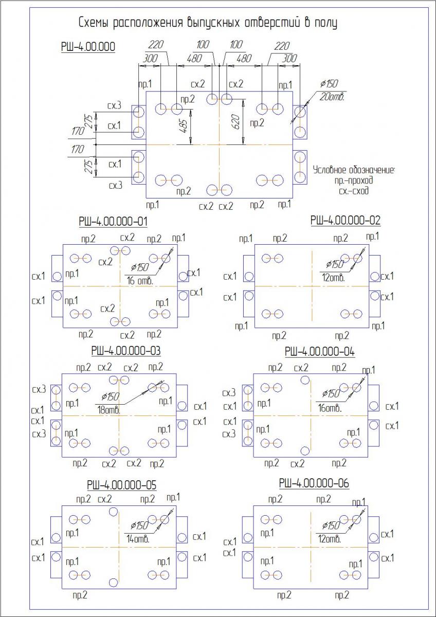
Floor outlet layout:
-
-
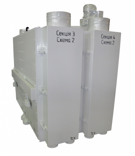
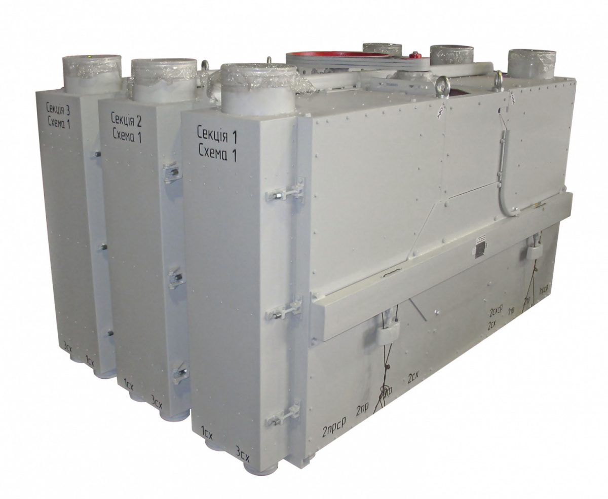
Layout of sieve sections РШ-6:
-
-
Layout of sieve sections РШ-4:
-