Purpose:
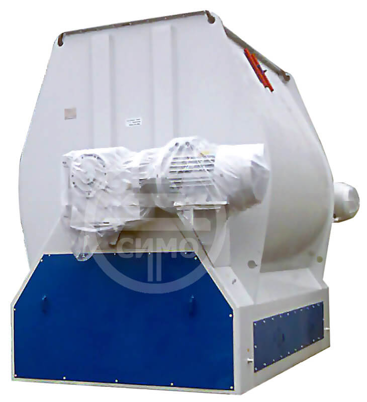
Batch operated horizontal scraping-blade mixer ЗСЛ-6000 is designed for mixing of compound feed components after batch dosing. Size of individual mixing components should be from 0.1 to 3.0 mm.
The Mixer can be applied at the he animal feed production plants and for production of enrichment mixtures. It is available to make the mixer Н-ЗСЛ-6000 (its details contact with mixing products, are made of stainless steel), this mixer is designed for mixing of different food concentrates or premixes.
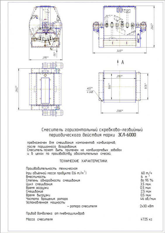
Specifications:
| Indicator name |
ЗСЛ - 6000 |
| 1. Technical capacity, kg/cycle, no more than |
3 000 |
| 2. Storage capacity, m3, no more than |
6 |
| 3. Mixing homogeneity rate, % |
95 |
| 4. Mixing cycle,minute., including: |
3,5 |
| - time of load |
0,5 |
| - time of mixing |
2,5 |
| - time of upload |
0,5 |
| 5. Rotor speed, rpm |
46 ± 3 |
| 6. Installed capacity, kW |
2 х 30 |
| 7. Dimensions, mm: |
|
| - length |
3 410 |
| - width |
2 115 |
| - height |
3 645 |
| 8. Weight, kg: |
4 725 |
The principle of mixer operation:
The principle of mixer operation is as follows: ingredients entering to the mixing hopper accumulate until a portion/level is reached, then dosed components in manual mode (the short loading time prevents the effect of component separation). In the mixer body, components under rotation of the rotor are subjected to intensive back mixing by paddles. After the mixing time has elapsed, the bomb bay opens and the resulting mixture is sent to the place of unloading from the hull. The unloading is controlled manually or using automation / computer.
Mixer structure is:
Mixer consists of: body – 1, rotor – 2, drives – 3, bomb door – 4, bomb door pneumatic drive – 5, bomb door lock against opening - 6.
The body 1 is a steel welded structure, semi-cylindrical. In the side walls of the mixer body there are windows closed with covers, interlocked with the electric motor by limit switches and intended for repair work, visual control and periodic cleaning of the mixer from the inside with a scraper and pneumatic tool.
Rotor 2 is a shaft with 6 blades (scrapers). The blades are located at certain angles, which provides intensive mixing of the loaded product. The rotor shaft is supported by bearings mounted on the mixer body. Drive-3 provides a given rotor speed from the electric motor through a gearbox. Bomb unloading-4 consists of two doors, curved along a radius, with welded plates and stiffeners. The leaves are attached to the shafts using levers. The opening and closing of the bomb bay doors is performed using pneumatic cylinders of the bomb bay-5 pneumatic drive, which, by means of levers and key connections, rotate the doors around the axes of the shafts installed in the bearing assemblies at the required angle of rotation corresponding to the positions: open and closed.
The bomb bay 6 support device consists of locks located on the shaft, which lock the bomb bay from possible opening during product mixing. The locks work synchronously and are driven by a pneumatic cylinder, the rod of which is extended to the stop in its original state when the doors are closed. Flaps work as follows. In the initial position, the rods of the pneumatic cylinders are pushed in until they stop - the doors are closed. At the command of the control system, the pneumatic valve switches, the pneumatic cylinder rod of the back-up device moves in, turning the locks and releasing the leaf 1. After that, the rod of the pneumatic cylinder drive of the leaf 1 is extended to the stop, opening this leaf, then the rod of the pneumatic cylinder of the drive of the leaf 2 is extended, opening the leaf 2. After unloading the mixer, the shutters are closed in the reverse order. The backing device has adjustments to prevent poor closing of the flaps in the event of product sticking.
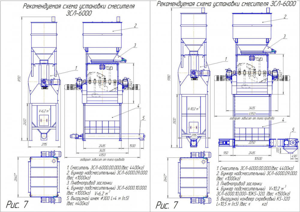
Recommended mixer installation scheme:


